표면 결정
모든 CT 기반 메트롤로지는 복셀 모델에서의 정확한 표면 결정에 기반합니다.표면 결정이 나아질수록 측정 불확실성은 줄어듭니다.
표면 결정:
- 측정 불확실성의 최소화를 보장합니다.
- 서브복셀 정확도와 로컬 적응형 알고리즘으로 세부 측정을 수행합니다.
- 주변 복셀의 음영 값에 따라 개별 복셀의 음영 값을 처리하여 단일 음영 값 임계값에 기반한 것보다 표면 결정이 훨씬 더 정확해집니다.
- 간격 기반 모드를 제공하여 자동화된 환경 및 음영 값 조건이 변하는 경우에도 정확도가 높은 로컬 적응형 표면 결정이 가능합니다.
- 한 볼륨 내의 다중 재질 표면을 동시에 결정하기 위한 다중 재질 모드를 제공하여 결과적으로 재질마다 하나의 구성요소가 생성됩니다.
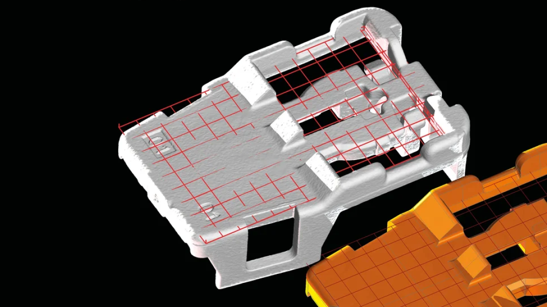
정렬
명목 부품 또는 좌표계에 대한 정렬은 측정 결과를 위해 결정적으로 중요합니다.이는 명목과 측정된 치수 사이의 추출 및 비교 및 조립된 부품의 검사를 가능케 합니다.
VG 소프트웨어를 이용하여:
- 포인트,표면 및 지오메트리 기반 접근법을 사용하여 데이터 세트를 참조 데이터 세트 또는 좌표계에 정렬합니다:
- 포인트 기반:RPS 및 3-2-1 정렬
- 표면 기반:제약 또는 부분 영역을 이용한 최적 맞춤 및 특징적 영역에 초점을 맞춘 피처 기반 정렬
- 지오메트리 기반:순차 정렬은 물리적 정렬의 모방을 가능하게 하여 지오메트리 대응 쌍을 하나씩 생성하여 자유도를 감소시킵니다.남아 있는 자유도는 전체 또는 부분 모델에 대한 최적 맞춤으로 해결될 수 있습니다.
- 정렬 결과의 품질을 평가하기 위한 허용 오차
- 정렬 변경 시 자동화된 업데이트를 제공하는 사용자 정의 및 로컬 좌표와 데이텀 좌표계를 사용
- 제조 주형 교정 모듈의 일환으로 비 강성 정렬을 사용
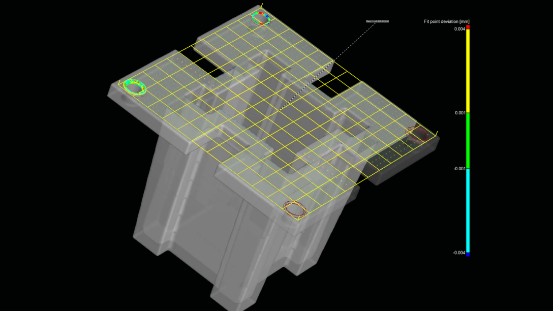
지오메트리 요소 맞춤
스캔으로부터의 지오메트리 요소 추출은 치수와 공차의 평가에 기본이 됩니다.
VG 소프트웨어를 이용하여:
- 스캔으로부터의 지오메트리 요소 추출
- "스마트 확장"을 통해 지오메트리 요소의 유형을 자동으로 인식
- 가장자리 거리,밀도,각도 편차,맞춤 방법(가우스 또는 Chebyshev)그리고 위치 또는 축에 대한 제한을 통해 지오메트리 요소의 맞추기를 제어
- PTB와 NIST*의 인증을 받은 알고리즘을 사용합니다
* PTB 및 NIST 인증:이 소프트웨어에 포함된 Volume Graphics Metrology Kernel VGMK 2023.1.0은"Evaluation software based on minimum-zone method for coordinate measuring machines"("좌표 측정기용 최소 영역 방법에 기반한 평가 소프트웨어")및"Evaluation software based on least-squares method for coordinate measuring machines"("좌표 측정기용 최소 제곱법에 기반한 평가 소프트웨어")에 대한 PTB 테스트를 통과하였고,NIST의"Algorithm Testing and Evaluation Program for Coordinate Measuring Systems"("좌표 측정 시스템을 위한 알고리즘 테스트 및 평가 프로그램")에 의해 검증되었습니다. 테스트 결과는 Windows(64비트)에서 얻은 것입니다.
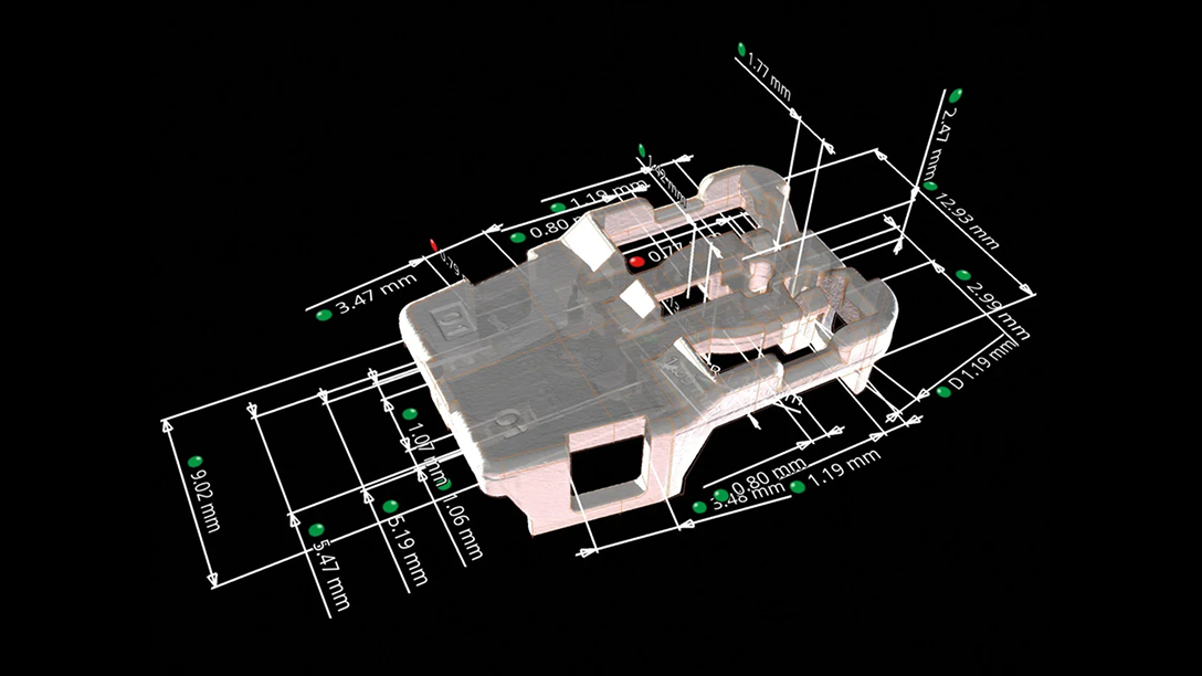
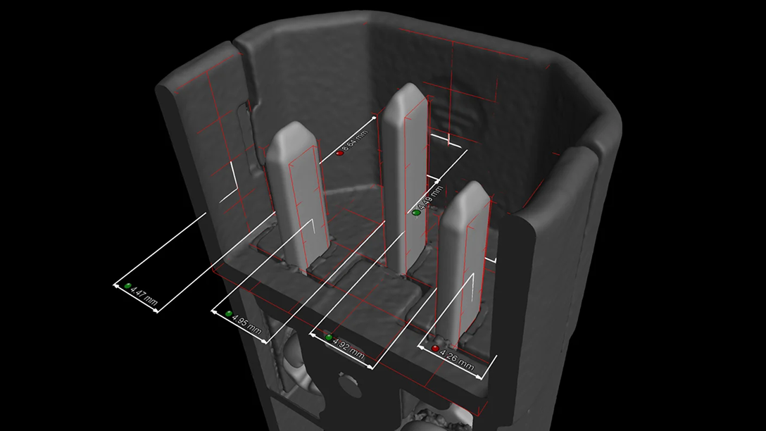
치수 측정
VG 소프트웨어에서는 사용자가 벌룬 번호로 이름,치수,허용 오차를 자동으로 설정할 수 있는 표준화되거나 개별 공차 표를 사용하여 2D 및 3D 치수를 측정할 수 있습니다. 물리적 좌표 측정 기기,시각적 스캐너 기능과 그 이상을 누려보십시오.
치수 측정 기능으로 다음이 가능합니다.
- 모든 요소에 대한 장면 트리나 표 형식의 오버뷰에서 장면의 지오메트리 요소를 선택함으로 2D와 3D 모두에서 거리,각도,반지름 등의 차원을 간편하게 생성합니다.
- 공칭 CAD,PMI 정보,개별 값 또는 허용 오차 표로부터 허용 공차를 할당합니다.
- 모든 투영 방향 값을 추출하고 보고합니다.
- 극도로 큰 측정 템플릿에 대한 정교한 필터 기능을 활용하여 장면 트리 안에서 피처 및 서브 피처를 식별합니다.
신속하고 점에서 점까지를 기반으로 한 거리와 각도 분석 및 주석에 대한 인스트루먼트를 사용합니다.
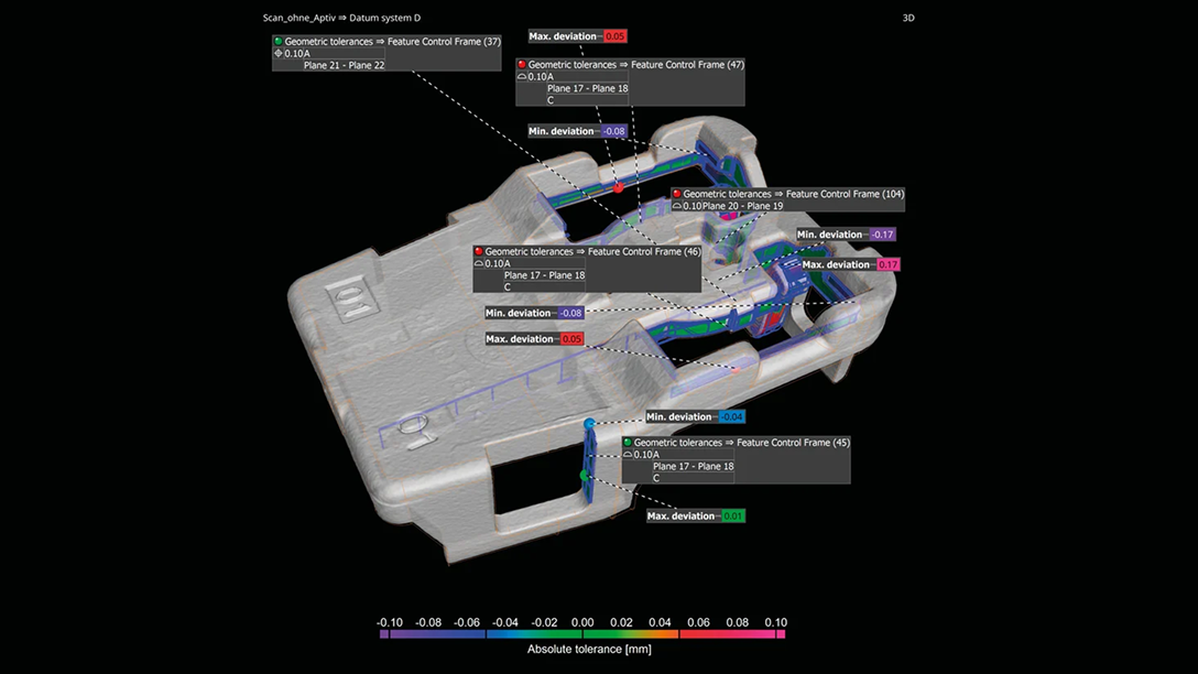
GD&T
VG 소프트웨어는 선 및 표면 윤곽도와 최대 재질 요구사항(MMR)을 포함한 위치 공차 등 모든 17개의 지오메트리 치수 측정 및 허용 오차(GD&T) 콜아웃을 지원합니다.
GD&T 기능:
- 모든 GD&T 콜아웃 지원
- ISO 또는 ASME 표준을 준수하고 지속적으로 업데이트함
- 복잡한(자유형)데이텀,선/표면 프로파일 분석 및 최소/최대 재질 조건 지원
- 로컬 좌표 및 데이텀 시스템 지원
- 가능한 한 쉽게 이해하는 색상 오버레이에서 GD&T 분석 시각화 허용
- 모든 복잡한 GD&T 정보를 상대적인 색상 맵으로 동시에 표시하여 사용자 친화적인 방법으로 전체 지오메트리 분석을 평가하도록 함
- 데이텀 시스템이 있든 없든 오버레이 표면 프로파일 콜아웃이 가능하고 동시에 결과를 시각화함
- 소프트웨어가 제공하는 시각적 단서에 기반하여 위치 편차 값과 방향 해석 활성화
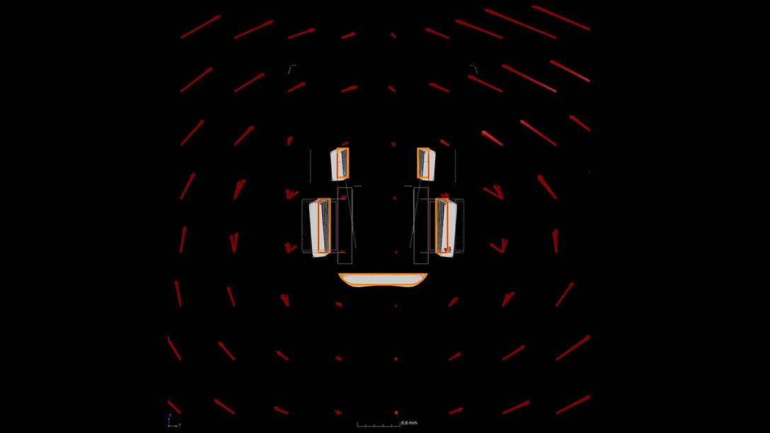
형태를 따르는 적응형 측정 템플릿
- 변형된 부품의 형태를 따르는 적응형 측정 템플릿을 사용하여 작업 시간을 50%이상 절약하십시오. 사출 성형 부품 또는 3D프린팅 부품의 첫 결과는 자주 허용 오차를 만족하지 않을 뿐 아니라 뒤틀려 있어,명목 CAD 객체에서 만들어진 측정 템플릿을 스캔에 적용하기가 쉽지 않습니다. 적응형 측정 템플릿을 이용하면,명목 CAD 데이터를 이용하여 생성되거나 PMI를 통해 가져온 측정 템플릿을 심하게 변형된 부품에도 쉽게 적용할 수 있습니다. 측정 점들은 실제 객체의 최적 위치에 생성되며 변형된 형태를 완벽히 따릅니다.
- 저장 좌표계가 더이상 필요하지 않으며 많은 시간이 소요되고 숙련된 노하우를 필요로 하는 피처의 수동 후작업이 필요하지 않습니다. 이 새로운 특허 기술은 이전에는 로컬 좌표계를 이용해야 가능했던 정확한 분석이 가능했던 왜곡된 부품에 치수 및 허용 오차를 적용할 수 있습니다.