
Surface determination
All CT-based metrology depends on an accurate surface determination in the voxel model. The better the surface determination, the smaller the measurement uncertainty.
Our surface determination:
- Ensures minimum measurement uncertainty.
- Is subvoxel-accurate and locally adaptive, allowing for the measurement of details smaller than a voxel.
- Processes grey values of individual voxels based on the grey values of the surrounding voxels, making surface determination markedly more accurate than relying on a single greyscale threshold value.
- Offers an interval-based mode that enables high-accuracy, locally adaptive surface determination, even within an automated environment and under changing grey value conditions.
- Offers a multi-material mode that allows for simultaneous determination of the surfaces of multiple materials within a volume, resulting in one component per material.
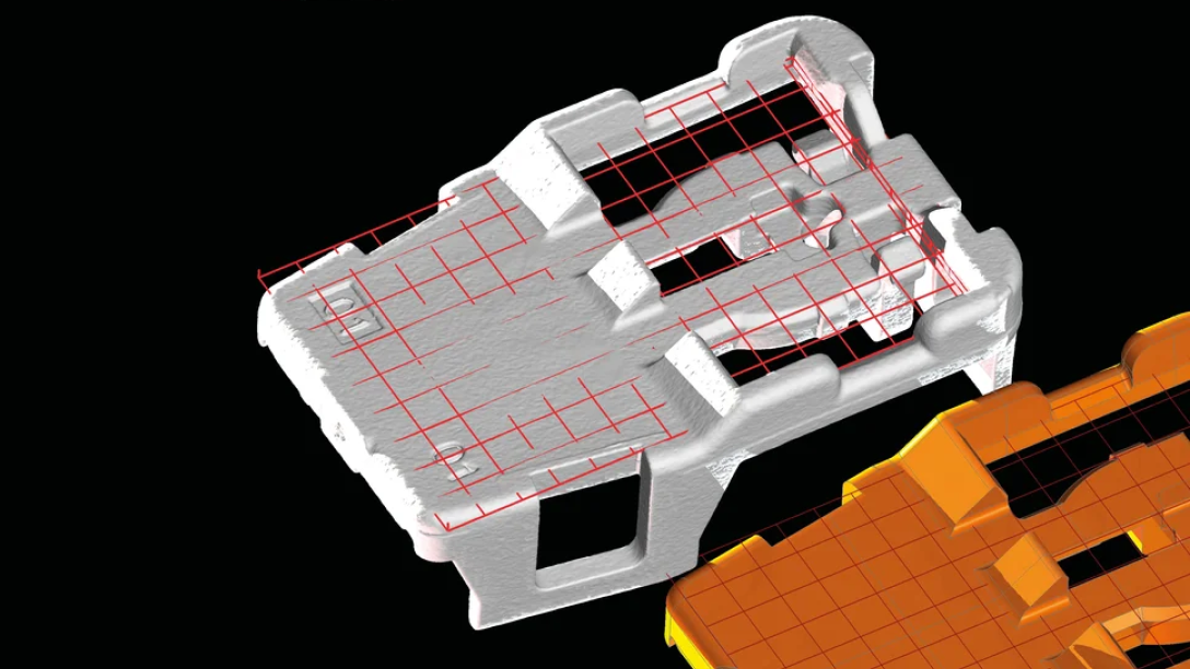
Alignment
Alignment to a nominal part or a coordinate system is crucial for measurement results. It enables the extraction and comparison of nominal and measured dimensions and the investigation of assemblies.
With VG software, you can:
- Align any data set to a reference data set or a coordinate system using point-, surface-, and geometry-based approaches:
- Point-based: RPS and 3-2-1 alignment
- Surface-based: Best fit, also with constraints or partial areas, as well as feature-based, focusing on characteristic areas
- Geometry-based: Sequential alignment enables the imitation of physical alignments, creating corresponding pairs of geometry one after another, thereby decreasing the degrees of freedom. The remaining degrees can be adjusted to achieve the best fit for the whole or partial model.
- Tolerance alignment results to determine their quality
- Use custom and local coordinate and datum systems, providing automated measurement updates when changing alignments
- Use a non-rigid alignment as part of the Manufacturing Geometry Correction Module
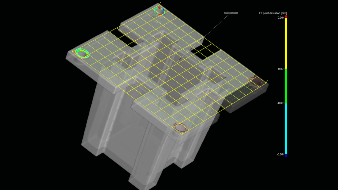
Geometry element fitting
Extracting geometry elements from scans is the basis for evaluating dimensions and tolerances.
VG software enables you to:
- Extract geometry elements from scans
- Automatically recognise the type of geometry element using "Smart Expand"
- Control geometry element fitting by border distance, density, angular deviation, fit method (like Gauss or Chebycheff), and constraining to a position or axes
- Use algorithms verified by PTB and NIST*.
* PTB- and NIST-verified: This software contains the Volume Graphics Metrology Kernel VGMK 2023.1.0, which passed the PTB test for “Evaluation software based on minimum-zone method for coordinate measuring machines” and the PTB test for “Evaluation software based on least-squares method for coordinate measuring machines” , and which was verified by the NIST “Algorithm Testing and Evaluation Program for Coordinate Measuring Systems”. The test results were obtained under Windows (64 bit).
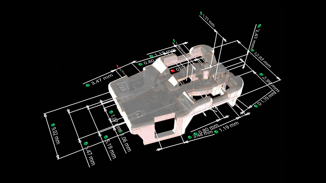
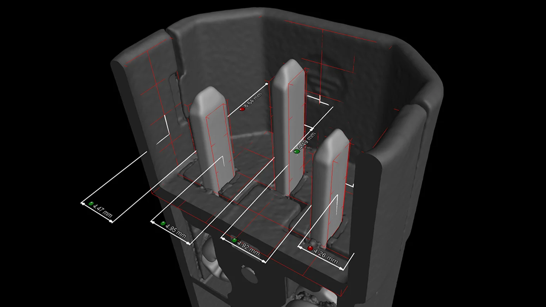
Dimensional measurement
In VG software, you can measure 2D and 3D dimensions using standardised or individual tolerance tables, which can even automatically set the name, dimension, and tolerance by balloon number. Enjoy all the functionality of a physical coordinate measurement machine, optical scanner, and more.
With the functions for dimensional measurement, you can:
- Create dimensions such as distances, angles, and radii in both 2D and 3D simply by selecting geometry elements on the screen, in the Scene Tree or the tabular overview of all elements.
- Assign tolerances from nominal CAD, PMI information, individual values or tolerance tables.
- Extract and report values in any projection direction.
- Utilize sophisticated filter functions for extremely large measurement plans to identify features and their sub-features within the scene tree.
Use instruments for quick, point-to-point-based distance and angle analyses and annotations.
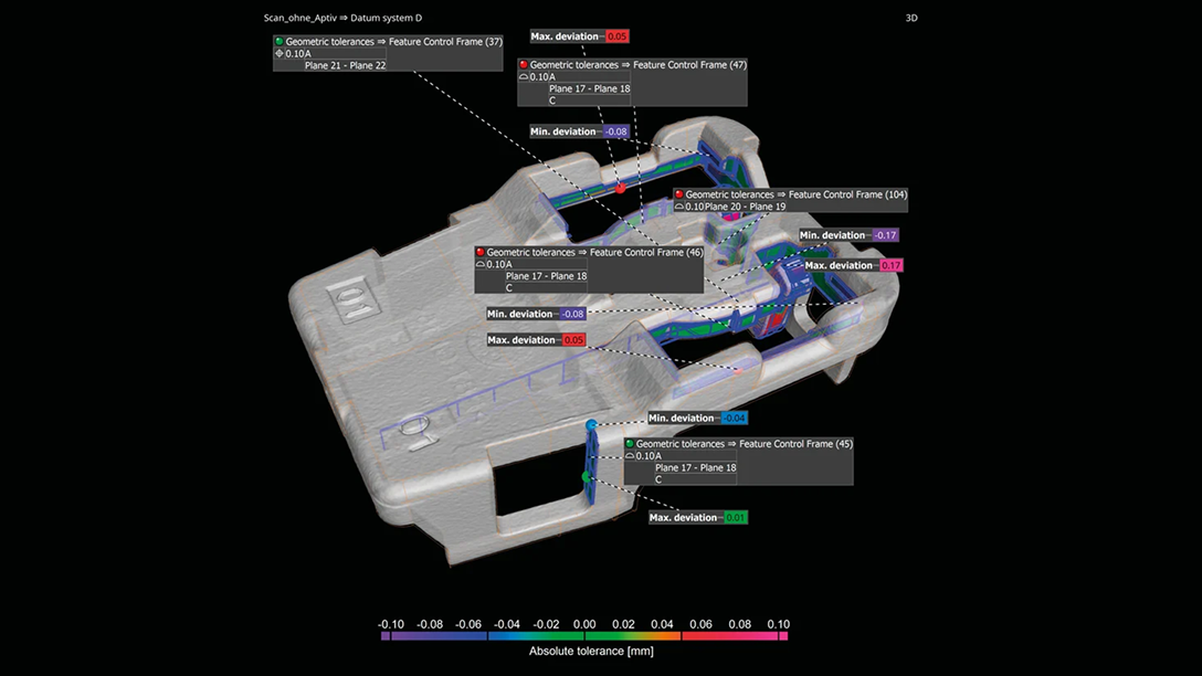
GD&T
VG software supports all 17 Geometrical Dimensioning and Tolerancing (GD&T) callouts, such as line and surface profile as well as position with maximum material requirement (MMR).
The GD&T functions:
- Support all GD&T callouts
- Are ISO or ASME norm compliant and continuously updated
- Support complex (free-form) datums, line/surface profile analyses, and min./max. material conditions
- Support local coordinate and datum systems
- Allow you to visualize GD&T analyses, where possible, as easy-to-understand colour overlays
- Allow you evaluate the overall geometrical analyses in a user-friendly way by simultaneously displaying all complex GD&T information with a relative colour map
- Can overlay surface profile callouts with and without datum systems and visualise results at the same time
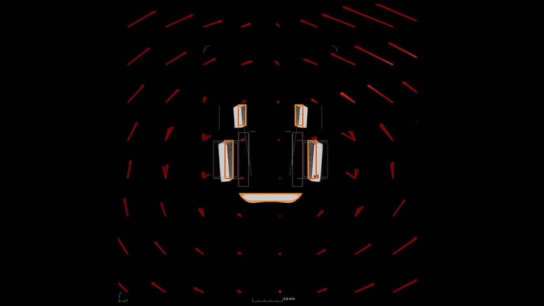
- Enable you to interpret the value and direction of position deviations based on visual clues given by the software
Shape-following adaptive measurement templates
- Save 50% or more time with adaptive measurement templates that follow the shape of distorted parts. First articles of injection-moulded parts and 3D-printed parts are often not only out of tolerance but warped in such a way that a measurement plan created on the nominal CAD object cannot be applied to the scanned part. With adaptive measurement templates, a measurement plan created using the nominal CAD data or imported via PMI can be easily applied to even strongly deformed parts. The measurement points are placed at the optimal positions on the actual part and perfectly follow the distorted shape.
- You no longer need storage systems or time-consuming manual post-processing of features by highly skilled users. This new, patented technology enables the application of dimensions and tolerances to distorted parts, where only local coordinate systems would previously have permitted a correct analysis.
Contact us today—our team is ready to assist!
Request a quote