
Tool correction features
Use the manufacturing geometry correction functions to optimise your tools or 3D printing geometries. The software uses scans of your sample part to calculate suggestions for necessary changes to tools and moulds in order to minimise iterations.
With this module, you can:
- Optimise the mould to compensate for part warpage and shrinkage
- Correct the tool based on points, curves, or surfaces to assist the mould maker in redesigning the product
- Compensate the part if the mould is created parametrically from it
- Reverse engineer surfaces on the scan
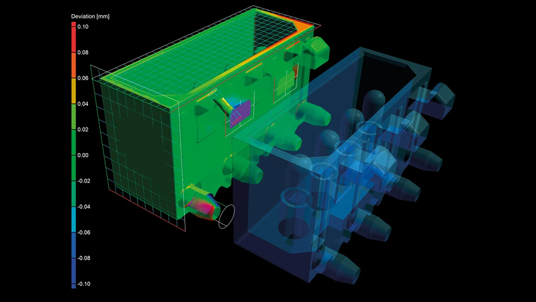
The software uses scans of your sample part to calculate suggestions for necessary changes to tools and moulds.
Use the manufacturing geometry correction features to compensate and export points.
Compensate and export points
To compensate and export points, which can also be based on user input, you can use the manufacturing geometry correction features to:
- Replicate the typical workflow in which only arbitrary or defined points are chosen, compensated, and exported as a .csv file for the mould maker.
- Use a more sophisticated workflow incorporating cubic surfaces of the part or mould, which are based on a set of points rather than surfaces. This enables a parametric workflow in the CAD system, replacing the source points with the compensated points.
- Import specific points and export their compensated descendants as a .csv file.
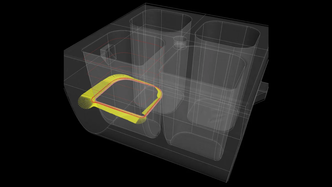
Compensate and export sections and curves
To compensate and export sections and curves, you can use the manufacturing geometry correction features to:
- Work on areas forming a closed loop in the part, such as sealing surfaces or cavities, which are often too narrow or complex to be compensated by single surfaces.
- Compensate a section, enabling the CAD system to perform simple lofting functions with draft angle. This approach allows for more control and therefore higher manufacturability than using free form surfaces.
- Export the section information as curves or points.
Compensate surfaces and patch compounds
To compensate surfaces and patch compounds using a rigid realignment while adhering to manufacturing constraints, you can use the manufacturing geometry correction features to:
- Only move a mould while keeping the parametrisation and shape of it. This ensures easier reintegration into the CAD model, improved manufacturability, and the creation of milling strategies that are easier to develop compared to creating free-form geometry.
- Create constraint canonical geometry with constraint size and orientation, i.e., fit a cylinder with a specific diameter and orientation to a compensated point cloud.
- Split entire patch compounds from the CAD model and realign them to a compensated point cloud while maintaining control over all degrees of freedom.
Replace geometries with free-form surfaces
To replace geometries with free-form surfaces while maintaining full control over their parametrisation and smoothness, you can use the manufacturing geometry correction features to:
- Achieve the best compromise between accuracy, smoothness, and manufacturability by interpolating points in an iterative process.
- Create free-form surfaces with a defined number of control points, smoothness, and tension, and visualise the deviations and quality of the surface.
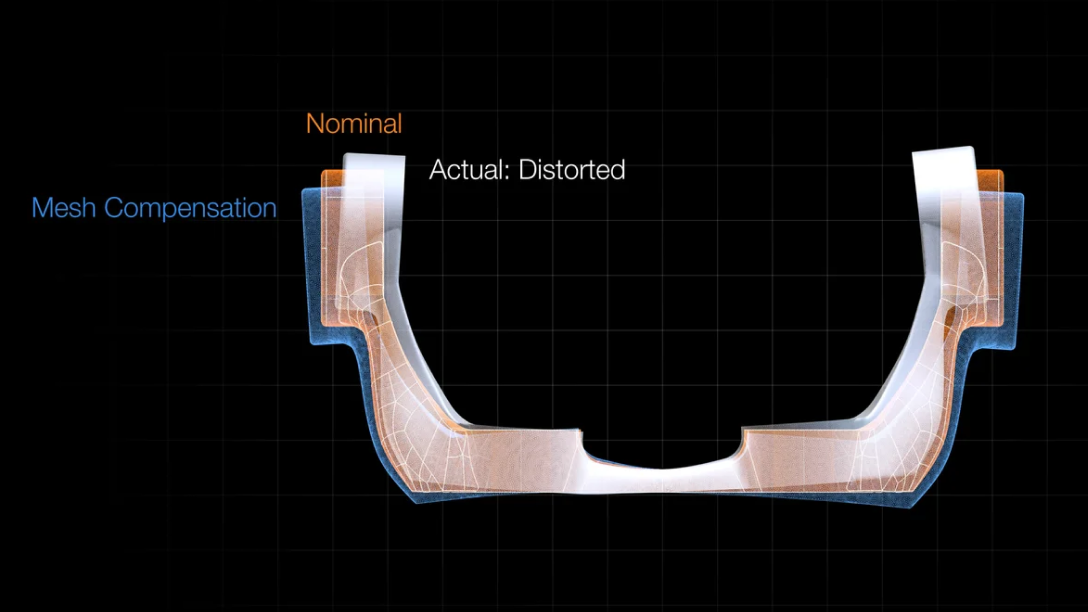
Mesh compensation features for 3D printing
Additively manufactured parts are often deformed. Such distortions are inherent in the 3D printing process and may even remain after completing a previous optimisation based on a 3D printing simulation. You can easily create a surface mesh that compensates for the difference between the actual object and reference object directly from the CT scan using mesh compensation (part of the Manufacturing Geometry Correction module).
With mesh compensation, you can:
- Compensate the mesh sent to a 3D printer to eliminate deviations in the actual geometry caused by distortions such as warpage from internal stresses, uneven heat, and uneven volume distribution. Creating compensated, print-ready meshes reduces the time to market compared to the conventional trial-and-error approach.
- Add the remaining deviations of a print based on compensated data to the first corrected mesh to allow for a second compensation iteration.
- Use the full spectrum of functionality within the metrology package, such as alignments, GD&T analyses, or creating a golden surface to average the overall deviation of a batch of parts.
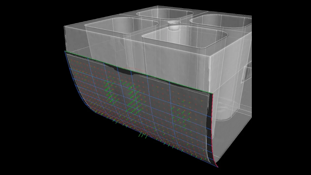
Compensate the mesh to eliminate deviations in the actual geometry caused by distortions such as warpage.
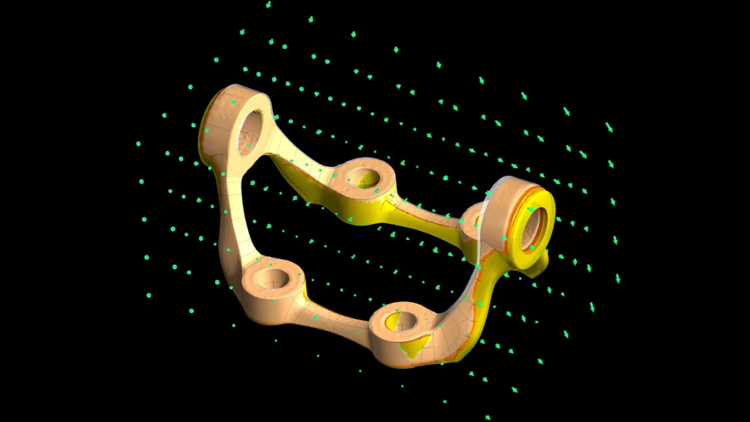
Arbitrary anchor points are perfect for organically shaped geometries.
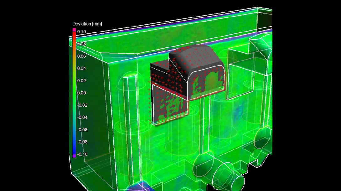
Arbitrary, defined, and gridded anchor points
Chose arbitrary, defined, or gridded anchor points for the compensation:
- Arbitrary anchor points are perfect for organic, smooth-shaped geometry.
- Gridded anchor points are perfect for complex geometry with a lot of small details.
- Defined anchor points are ideal for parts that contain important mechanical elements.
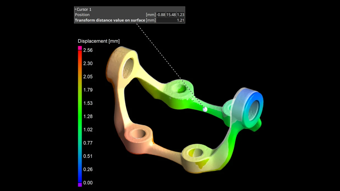
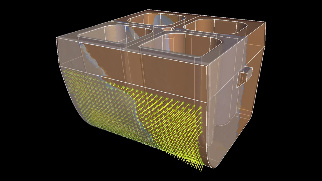
Use mesh compensation to visualise displacement and to create annotations.
Visualise distortion
Mesh compensation often lets you visualise, understand and document part distortion better than a nominal/actual comparison because a nominal/actual comparison may fail to show the deviation of overlapping areas even if the region has moved.
With mesh compensation, you can:
- Visualise displacement of the whole part
- Create annotations
Contact us today—our team is ready to assist!
Request a quote