
Mechanical simulation directly on CT scans
Working directly on voxel data, our easy-to-handle finite element (FE) simulation:
- Can be used to apply static mechanical loading by choosing between directed force, torque, and pressure
- Can be used to simulate material probes as well as components for both mono- and multi-materials with linear-elastic material properties
- Makes it very simple to build simulation models even for highly complex structures such as foams or components with microporosity, as well as biomechanical structures
- Utilizes subvoxel-accurate, local adaptive surface determination
- Calculates stress concentration around microdefects by incorporating the results of a porosity analysis run using any algorithm in VGSTUDIO MAX with a single click
- Provides a seamless workflow from segmentation to structural simulation within a single software

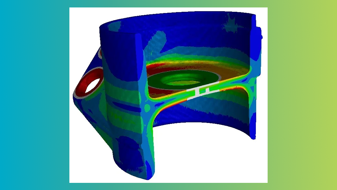
Stress analysis on a bionically optimized aeronautic structural bracket

Compressed material sample of open aluminum foam

Stress concentration at individual pores in a component

Loaded snake fang (Causus rhombeatus ) with visualized force lines showing the simulated bite force (Data from du Plessis, A., le Roux, S. G., & Broeckhoven, C. (2016), scan from Stellenbosch CT Scanner Facility)
Results
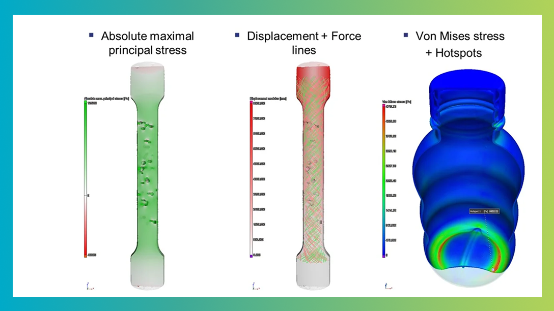
See your results directly on the scan of the real component:
- Calculate and visualise von Mises stress and strain, as well as the maximum principal stress, for evaluating the plastic yield limit or estimating rupture risk.
- Visualise the stress tensor field as force lines that illustrate the direction of the eigenvectors of the stress tensor, with their length corresponding to the magnitude of the corresponding eigenvalues.
- Display the magnitude of displacement, colour-coded at each point in the calculated volume, to visualize the calculated deformation.
Stress concentration at hot spots
Identify critically loaded areas in your part:
- Detect and visualise local maxima of von Mises stress, maximum shear stress, and maximum principal stress, and detect the magnitude of displacement.
- Identify and visualise connected areas in which the selected stress component or displacement exceeds your specified threshold.
Detect and visualise local maxima of von Mises stress
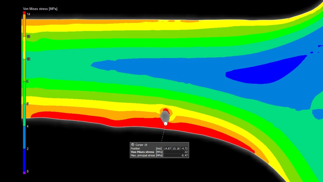
Calculate the maximum value (hot spot) of a selected stress component
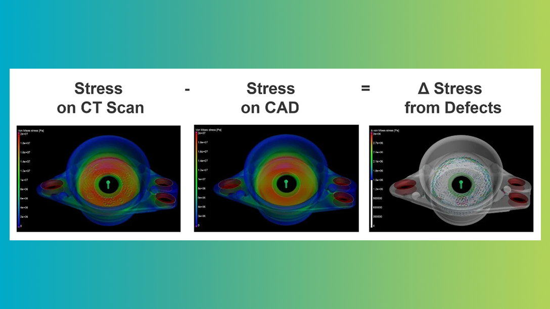
Comparison with CAD-based simulation
Compare simulation results based on the CT data of your actual part with simulations on the corresponding CAD model:
- Simulate both the CAD model and the actual part with all its discontinuities and shape deviations.
- Automatically compare two simulation results for the same or similar object, including von Mises stress, maximum principal stress, maximum shear stress, or magnitude of displacement.
- Calculate the difference of the respective values for each point of the structure and visualise the color-coded results on the part.
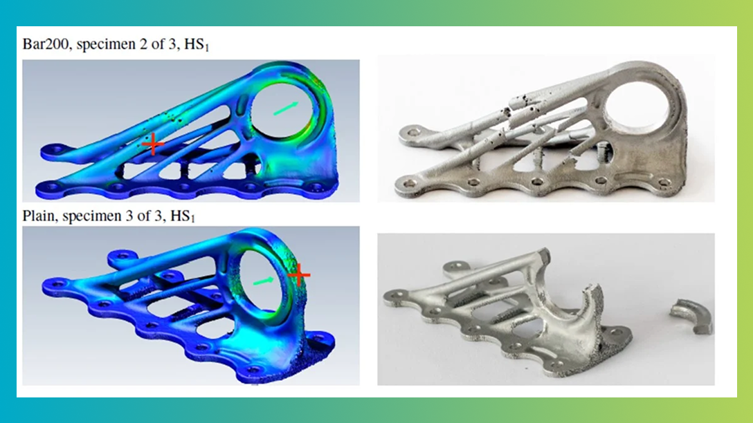
Validated results
The simulation method in the Structural Mechanics Simulation module has been numerically validated against conventional finite element analysis results, showing good agreement. It has also been experimentally validated against physical tests, which have shown that it is capable of identifying the most likely locations of failure in a structural component. (Predicting Failure in Additively Manufactured Parts Using X-Ray Computed Tomography and Simulation, Peer Reviewed Paper, 7th International Conference on Fatigue Design 2017)
Contact us today—our team is ready to assist!
Request a quote