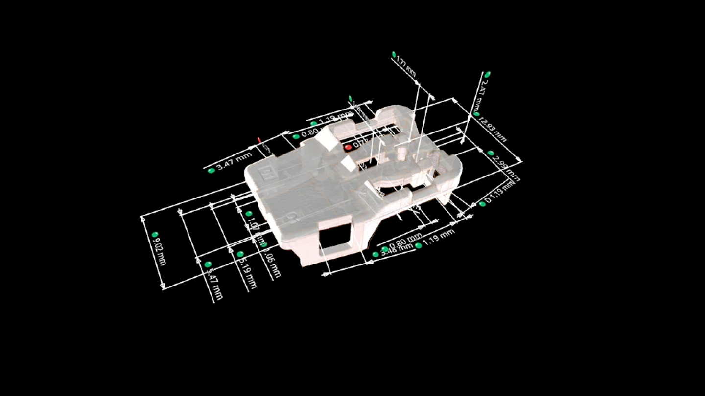
In VG software, you can measure 2D and 3D dimensions with standardized or individual tolerance tables that even automatically set name, dimension, and tolerance by balloon number. VG gives you all the functionality of a physical coordinate measurement machine, optical scanner, and more.
With the functions for dimensional measurement, you can:
- Create dimensions such as distances, angles, and radii in both in 2D and 3D, simply by selecting geometry elements on the screen, in the Scene Tree or in the tabular overview of all elements.
- Assign tolerances from nominal CAD, PMI information, individual values or tolerance tables.
- Extract and report values in any projection direction.
- Use sophisticated filter functions for very large measurement plans to locate features and their children in the scene tree.
- Use instruments for quick, point-to-point-based distance and angle analyses and annotations.

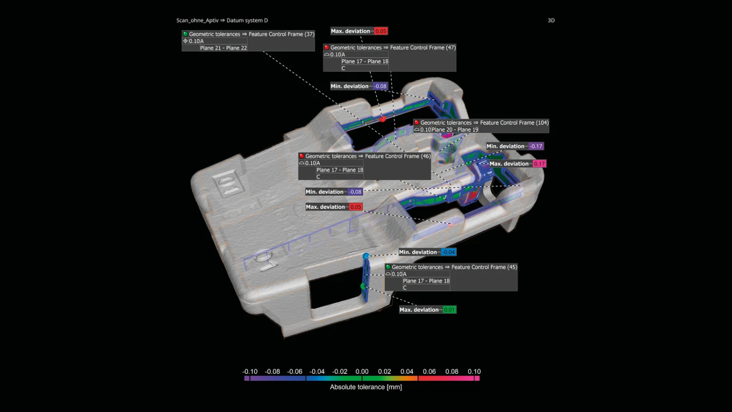
VG software supports all 17 Geometrical Dimensioning and Tolerancing (GD&T) callouts, such as line and surface profile as well as position with maximum material requirement (MMR).
The GD&T functions:
- Support all GD&T callouts.
- Are ISO or ASME norm compliant and continuously updated.
- Support complex (free form) datums, line/surface profile analyses, and min./max. material conditions.
- Support local coordinate and datum systems.
- Allow you to visualize GD&T analyses, where possible, as easy-to-understand colour overlays.
- Allow you evaluate the overall geometrical analyses in a user-friendly way by simultaneously displaying all complex GD&T information with a relative colour map.
- Can overlay surface profile callouts with and without datum systems and visualize results at the same time.
- Enable you to interpret the value and direction of position deviations based on visual clues given by the software.

For the localisation of insufficient or excessive wall thickness or gap width
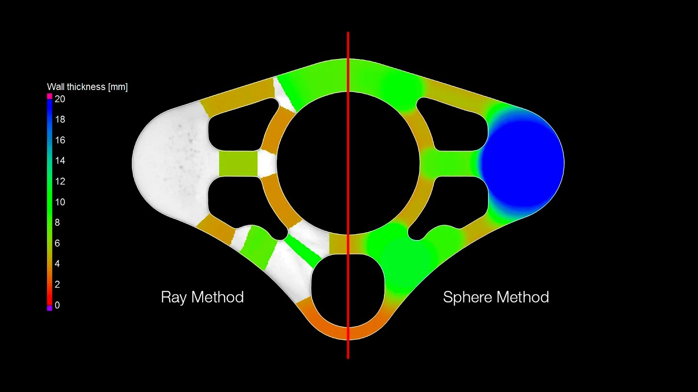
Perform volumetric analyses of a part’s thickness quickly and automatically—either using the ray method for parts with simple shapes or the sphere method for more organic shapes, including complex 3D printed parts. Colour-coded results help you localise areas with an insufficient or excessive wall thickness or gap width within the voxel, point cloud, mesh, or CAD data set.
The wall thickness analysis features:
- Automatically and quickly analyse the wall thickness.
- Offer two different, dedicated methods for cubic and organic parts, respectively:
- For parts with near-parallel surfaces, the ray-based method delivers the best results.
- For organic, curved or even branching surfaces, the sphere method is preferable, especially for complex 3D printed shapes that are topology optimized, generatively designed or even lattice structures.
- Locate areas with an insufficient or excessive wall thickness or gap width automatically and directly within the voxel, point cloud, mesh, or CAD data set.
- Allow the application of tolerances with various parameters, e.g., thickness (minimum, maximum, mean, deviation).
- Reduce the number of false detections with a noise filter, which is especially helpful for automated inspections.

